Microcontroller Project: Gesture-Controlled Robot Arm
For the end project of my microcontrollers course we were given an STM32 board and had to build something around it. I wanted it to be about robot arms, so the board became the controller of a 6-axis arm I designed and built, and its gyroscope and accelerometer steer the arm with the tilt of the board.
Tilt forward and the arm moves in positive X, backward is negative X, side to side is Y, up and down is Z. The inverse kinematics run in Python. The microcontroller was my excuse to do a mainly mechanical project.
The mechanics
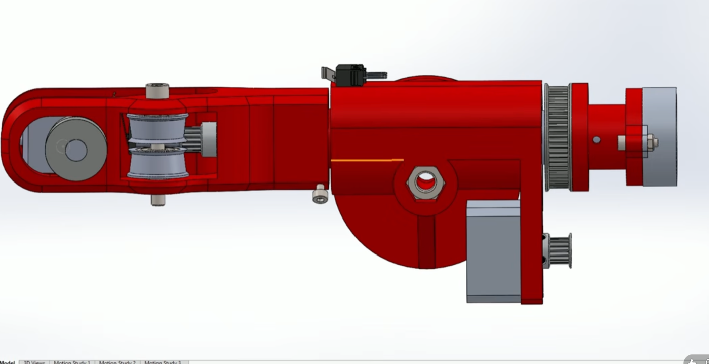
The arm is built the way 3D printers are: every joint has its own stepper driving a belt loop onto a large printed pulley, and everything else is printed too.
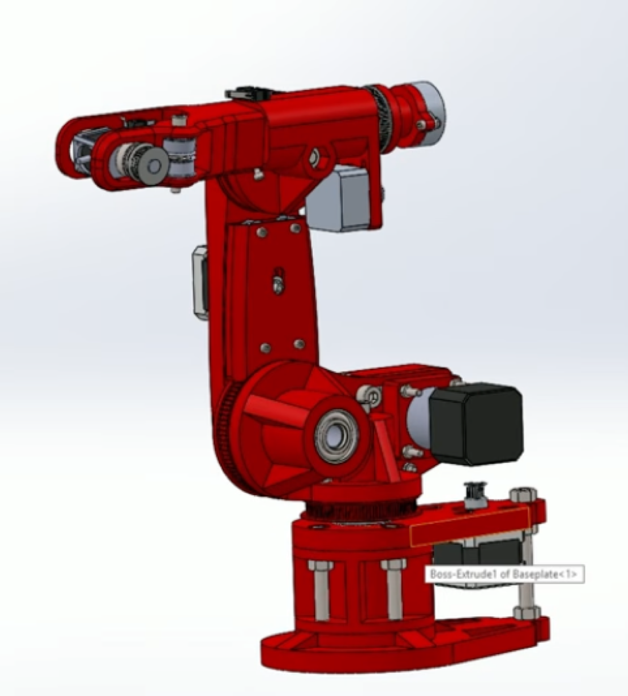
The base and shoulder sit on thrust bearings around an aluminium rod. The shoulder motor has a 5:1 planetary reduction and its belt runs past two 608 bearings as idlers onto an 80-tooth pulley.
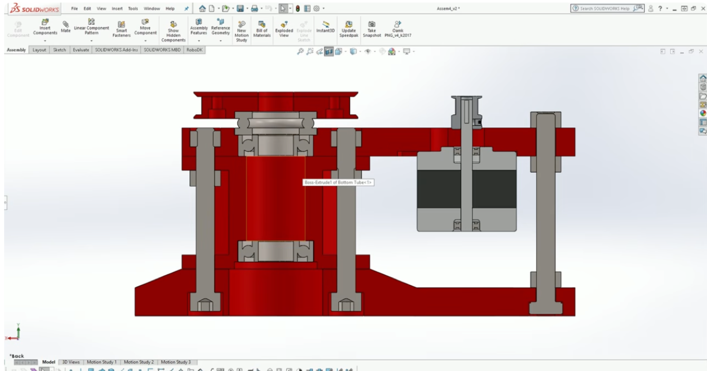
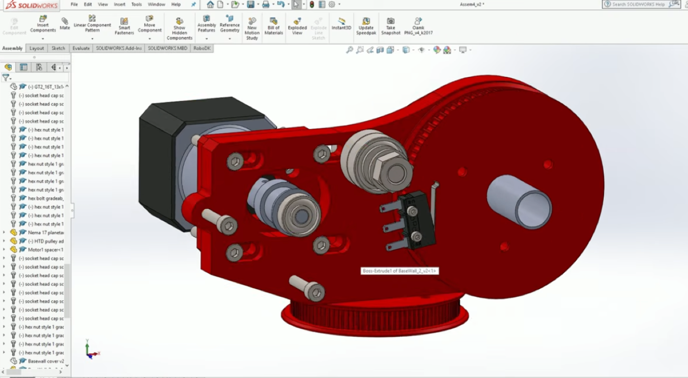
The elbow motor sits lower down to cut the moment of inertia of the joint, with adjustable idlers to set the belt tension.
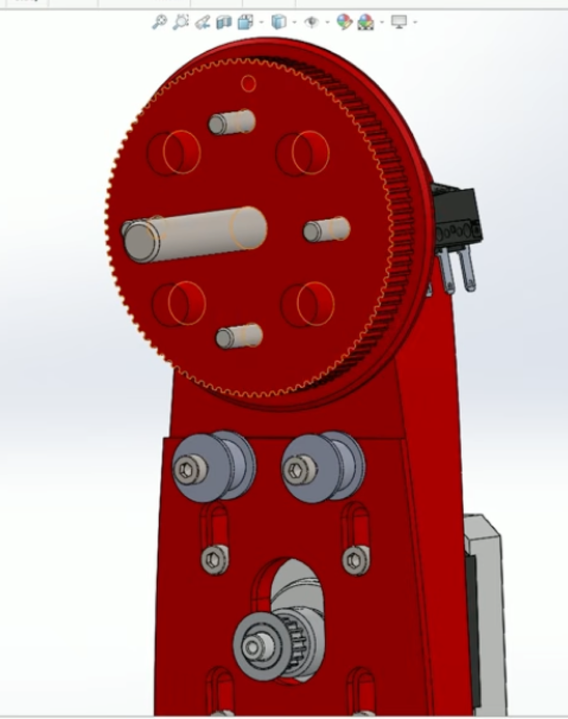
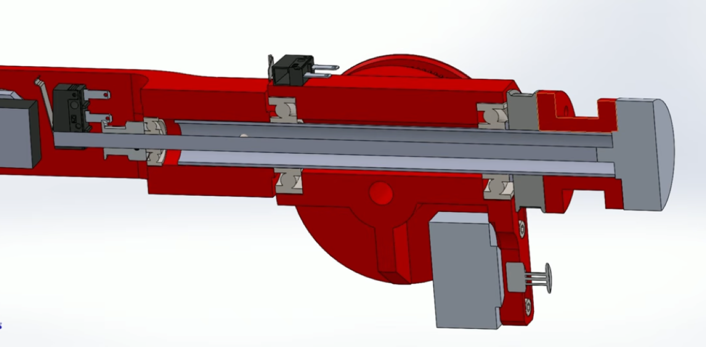
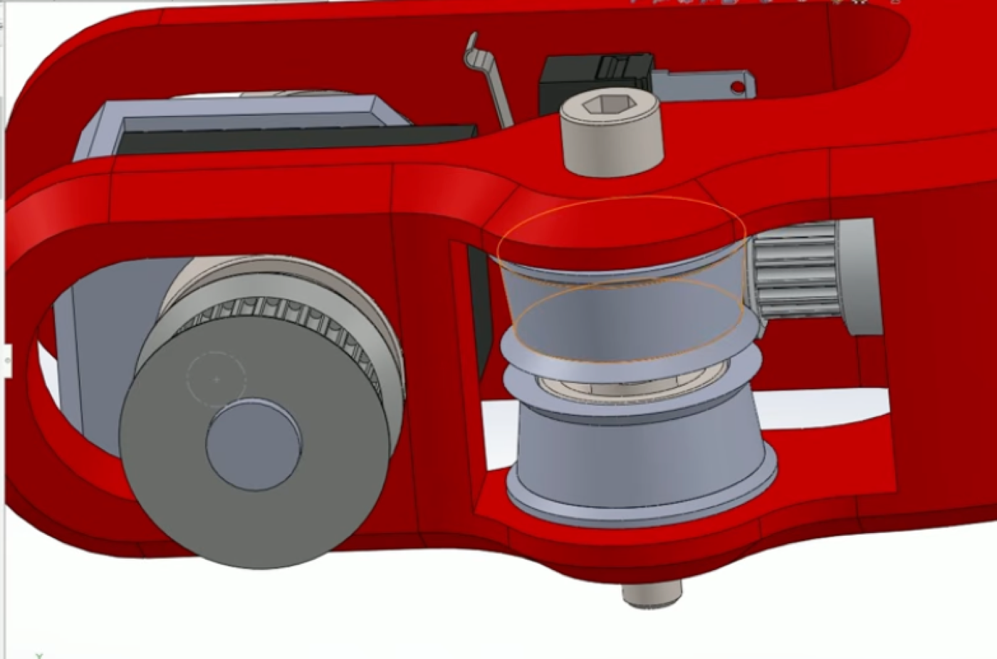
The forearm is the tricky part. A pancake stepper turns the wrist, and a small round stepper at the back drives a long thin rod through the forearm to the front, where the belt twists 90° over two chamfered idlers to move the last joint. The heavier motors stay near the elbow, so the arm carries little weight at the tip.
The electronics
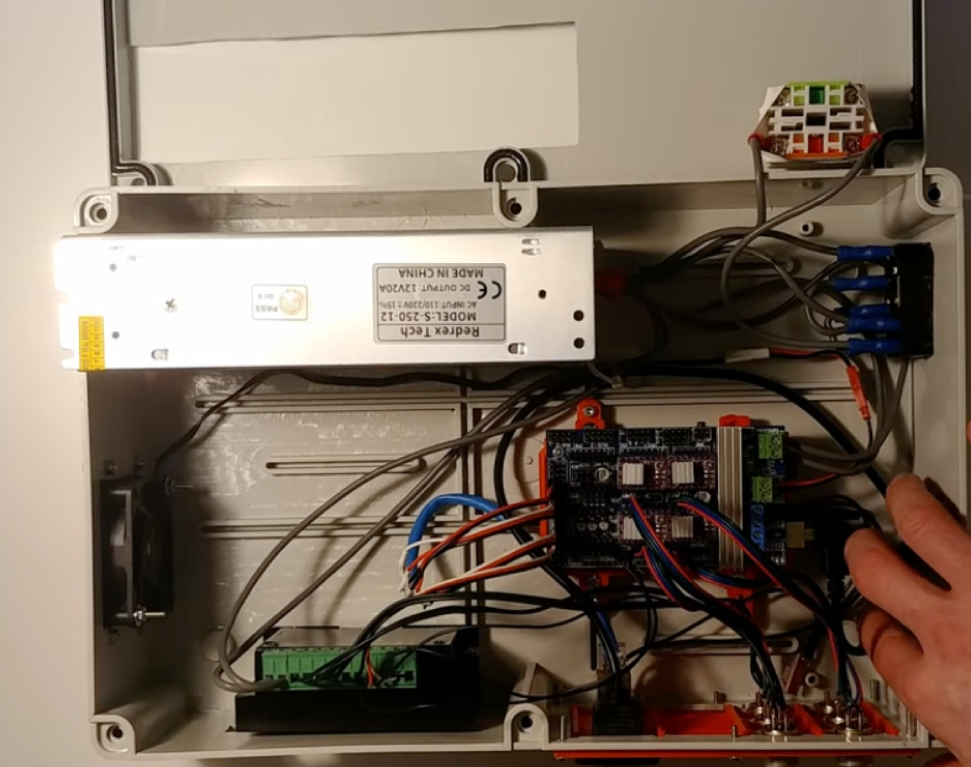
Everything electrical lives in a separate box: an IEC inlet through an emergency stop into a 12 V, 20 A supply, and an Arduino on a RAMPS board with DRV8825 drivers, the same breakout 3D printers use. Every joint has a limit switch and homes into it at startup, again like a printer.
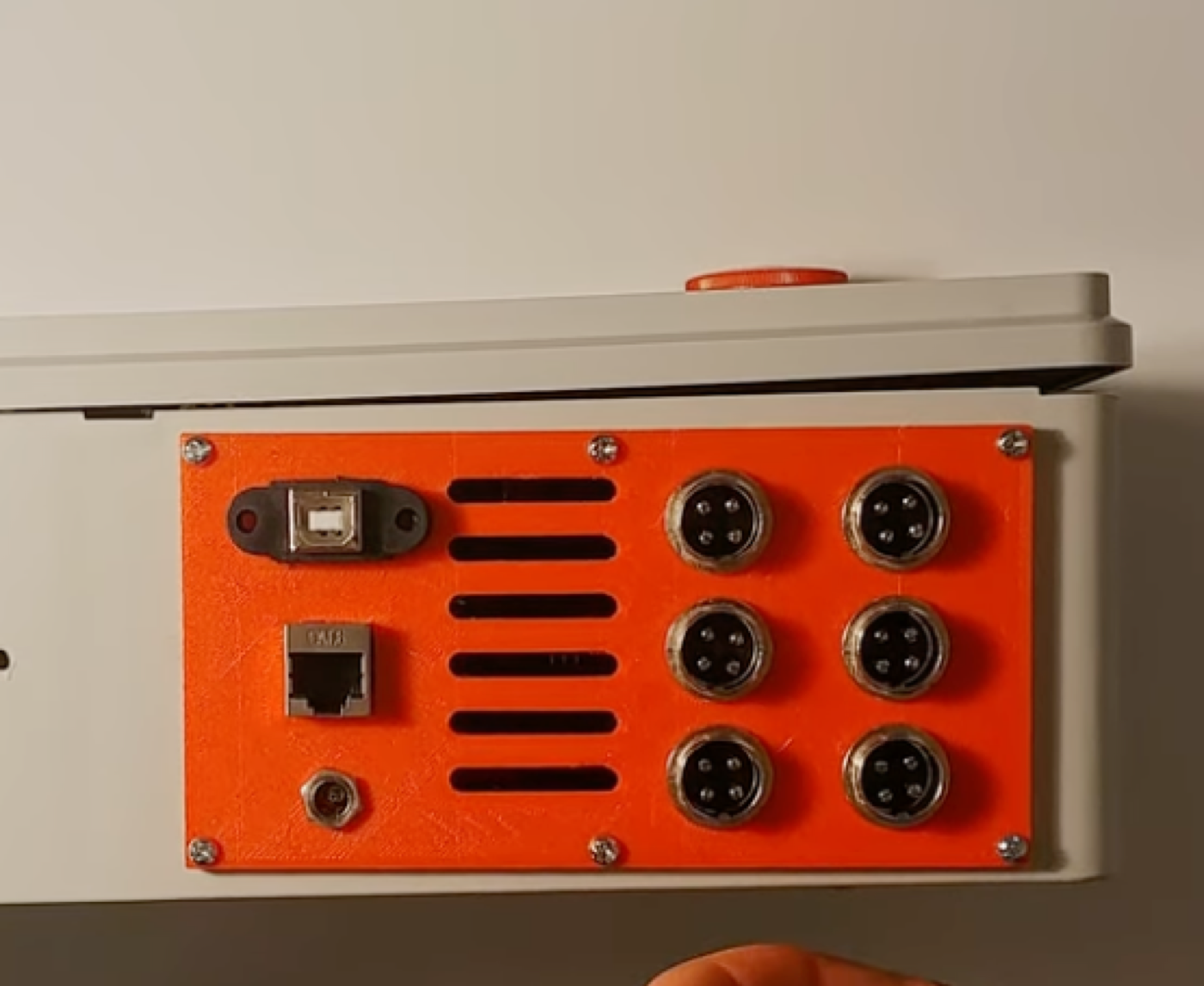
The side panel carries a USB-B pass-through, an RJ45 for the switch signals, a 5 V jack and one GX16 connector per motor.
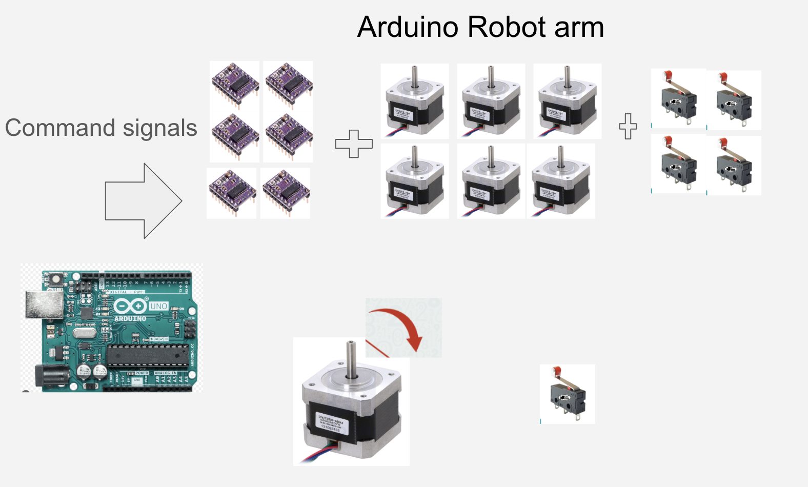
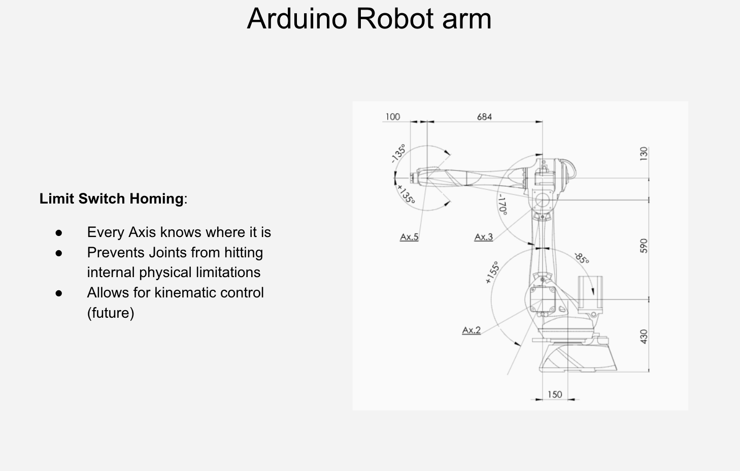
The workflow
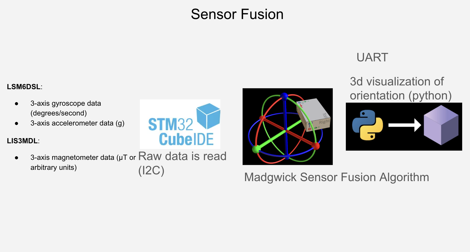
The board is the STM32 B-L475E-IOT01A, with a gyroscope, an accelerometer and a magnetometer on it.
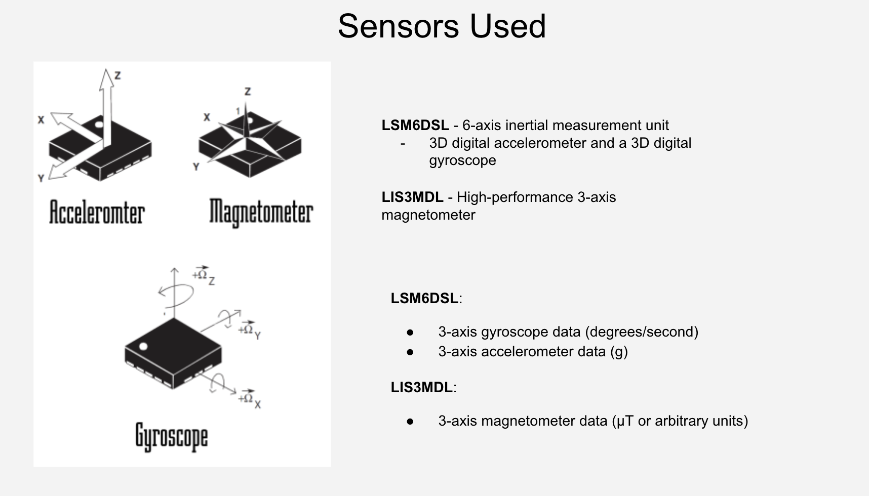
Reading the gyroscope and accelerometer on their own worked to an extent: the integrated gyro drifts, the accelerometer is noisy in motion, and yaw has no reference.
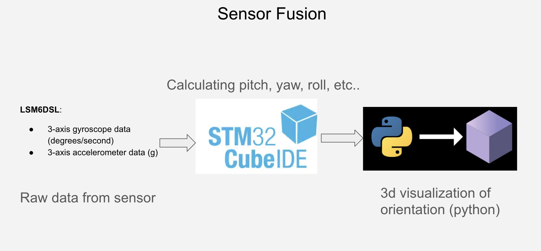
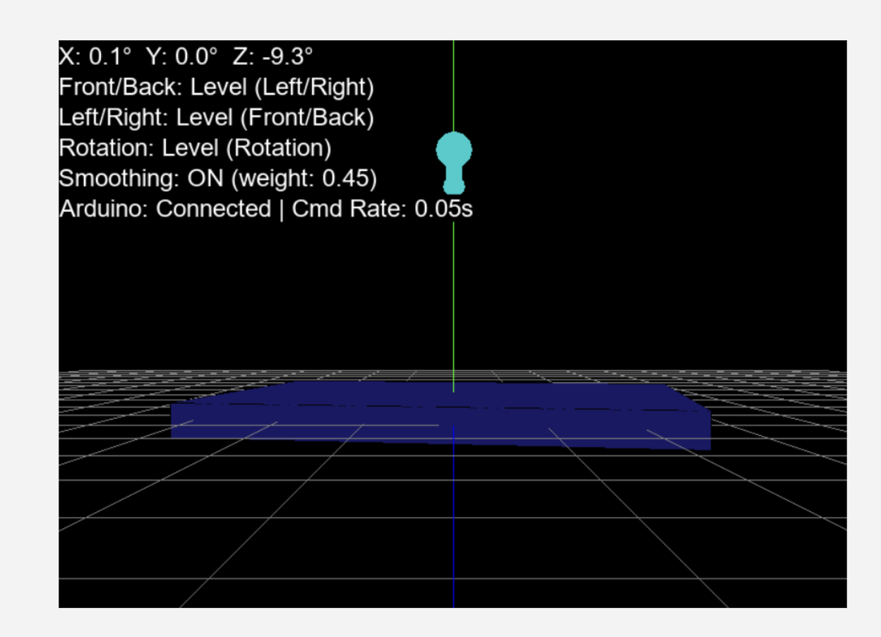
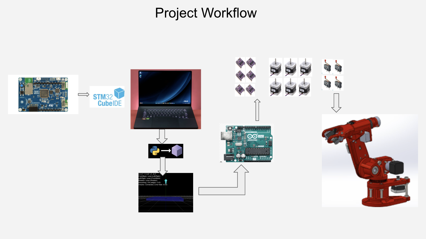
The chain that works: IMU over I2C, a Madgwick filter that fuses the sensors into a stable orientation, then Python, which shows the tilt on screen and only passes on tilts past 15°, so nothing moves by accident. Python sends the commands over serial to the Arduino, which drives the steppers.