6-Axis Servo Arm
In December 2024 I built a 6-axis robot arm out of hobby servos, 3D-printed parts and an Arduino UNO.
Servos keep the electronics simple. Each joint is one motor with a PWM line to the Arduino, no drivers and no limit switches, and the motor holds whatever angle it is given.
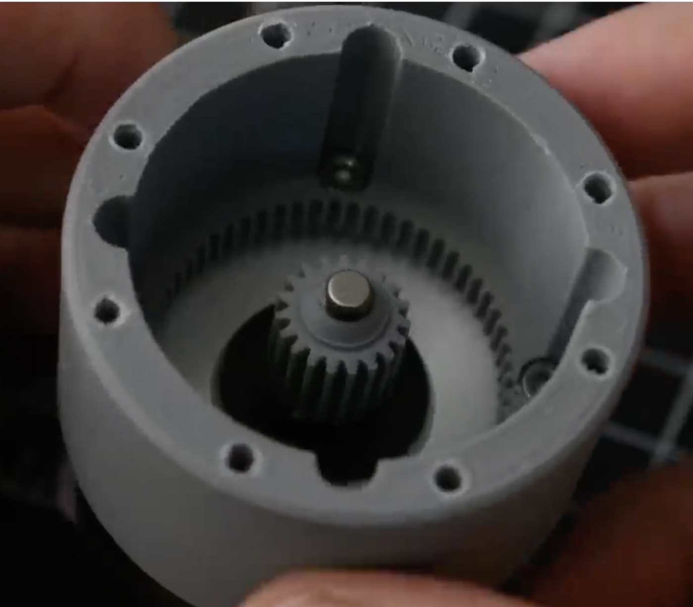
The servo horn on its own is not rigid enough, so I designed a 3D-printed housing for each motor to reduce the inaccuracy. Each housing holds a one-stage planetary reduction: the servo shaft drives a sun pinion, which turns three planet gears inside the printed ring gear, so the joint runs on the housing rather than on the horn. The rest of the body is printed as well.
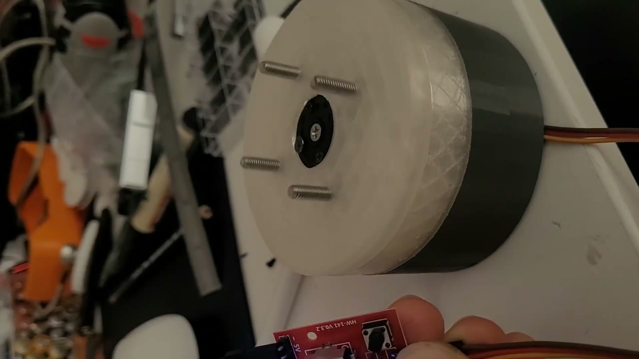
First test with the base mounted: jogging the rotation joint from the serial monitor.
Servos only know their own 0–180° range, so I had to center each motor. I sent 120°, 90° and 60° to joint 1 and checked that the link actually ended up at that angle.
I also used this setup to check that my kinematics code was outputting the correct joint angles. The Arduino computes the joint angles for a target, maps them onto the servo range and prints them to the serial monitor; if one of them falls outside 0–180° the target is reported as not reachable. To compare, I entered the same target in Maximilian Beck's robot GUI, which solves the inverse kinematics for a given robot geometry and shows the resulting pose.
After assembly the motors had to be centered again, and one servo cable broke. Replacing the cable was faster than disassembling the joint.
The finished arm is in the video at the top.
Limits
Servos have no absolute position reference and only 180° of range per joint, which is what bounds the arm's precision and reach.
The full video is on YouTube.